




Detail drawing

Detail drawings provide a detailed description of the geometric form of a part of an object such as a building, bridge, tunnel, machine, plant, and so on. They tend to be large-scale drawings that show in detail parts that may be included in less detail on general arrangement drawings.
Detail drawings may be used to demonstrate compliance with regulations and other requirements, to provide information about assembly and the junctions between components, to show construction details, detailed form, and so on, that would not be possible to include on more general drawings.
They may include dimensions, tolerances, notation, symbols and specification information, but this should not duplicate information included in separate specifications as this can become contradictory and may cause confusion.
They may consist of two-dimensional orthogonal projections showing plans, sections and elevations and may be drawn to scale by hand, or prepared using Computer Aided Design (CAD) software. However, increasingly, building information modelling (BIM) is being used to create detailed three-dimensional representations of buildings and their components.
Detail drawings may be confused with ‘detailed design drawings’ which might describe the drawings produced during the detailed design stage, (sometimes referred to as 'developed design' or 'definition'). Detailed design is the process developing the design so that it is dimensionally correct and co-ordinated, describing all the main components of the building and how they fit together. Not all drawings produced during this stage will necessarily be detail drawings.
They are also distinct from the definition of ‘working drawings’ which provide dimensioned, graphical information that can be used by a contractor to construct the works, by suppliers to fabricate components of the works or to assemble or install components. Again, not all working drawings will necessarily be detail drawings.
[edit] Related articles on Designing Buildings
- As-built drawings and record drawings.
- Assembly drawing.
- Building information modelling.
- Component drawing.
- Computer aided design.
- Concept drawing.
- Demystifying design processes of architectural details.
- Design drawings.
- Electrical drawing.
- Engineering drawing.
- Exploded view.
- General arrangement drawing.
- Geometric form.
- Installation drawings.
- North American Paper Sizes
- Notation and symbols.
- Packaging.
- Paper sizes.
- Production information.
- Projections.
- Residential design and 3D rendering.
- Scale drawing.
- Section drawing.
- Shop drawings.
- Specification.
- Technical drawing.
- Technical drawing pen sizes
- Working drawings.
Featured articles
Check out some of the best features and news from Designing Buildings as well as key stories from around the web.

Government approach could undermine delivery and regeneration.
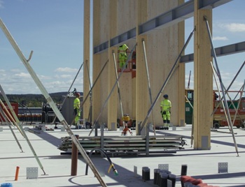
World's first mass timber data centre.
The overlooked environmental aspect of data centre development.
Introduction to radon awareness

New technical information sheet published by CIOB.

Updated supplier guide can help electrical contractors engage with NHP.

CIAT confirm the winners of the 2026 architectural technology awards.

Government launches a one stop shop for flood preparedness.

Sir Edwin Lutyens: Britain's greatest architect? Book review.

CIOB publishes free template to help assess and manage risks.
ECA's reflections on Party Conference season

Burnham wants to be confident of winning before asking for a fresh mandate.
New Chief Construction and Scientific Adviser

Sergio Cavalaro, Professor of Infrastructure Systems at Loughborough University.
Building safety levy for England

CIAT publish estimator tool for members.
Water sector faces a growing crisis that could slow the delivery of vital infrastructure.
Comments
what kinds of scales we r using for detail drawings ? metric & architectural
Thank you :)